DISCLAIMER: The modifications described in the following text are for educational purposes only. In no way do I recommend that you apply these modifications to your own motorcycle. If you do choose to go ahead and modify your motorcycle based on the information in this document you will accept all responsibility for your own actions. The author(s) of this document, and host(s) providing it for you, accept no responsibility whatsoever. If you are unqualified to make any of the changes described herein but are bent on doing the modification, seek out a knowledgeable friend or professional mechanic for assistance.
TTR250 bottom end engine strip and rebuild
NOTE: This is just a guide; it does not replace a service manual, general mechanical knowledge, specific motorcycle repair experience and good old common sense. With the proper tools, some general experience and this guide most users will be able to successfully service, replace or repair their starter motor . If you have any problems then stop and ask questions on the forum, take pictures of your point of confusion and get your answers before you start.
General information:
I am pretty sure that there isn't an existing pictorial guide to stripping down and rebuilding the TTR250 bottom end.
With the current interest in big bore kits that require the crankcases to be stripped for boring to take oversize sleeves I thought this would be a good time to create one.
The guide is created from a couple of threads that I created on the TTR250 forum so you may spot that the backgrounds of some photos differ but hopefully that isn't a distraction! Also, with the author's permission, I have used some photos and text from a thread created by Lindsay Mattingley on the TTR250 forum.
This guide is not a replacement for the Yamaha service manual. I recommend having that manual at hand which will prevent hours of head scratching and damaged parts. I can't emphasise this enough.
You need the correct hand tools, preferably a 1/4 drive and a 3/8 drive socket set, a range of metric Allen keys or equivalent hex square drive sockets, a torque wrench, a clean dust free workspace, and an M18 x 1.5 bolt or the correct flywheel puller to remove the flywheel.
A great tip from Lindsay is to get yourself a Pentel White 100WM marker pen for marking part orientation, location etc and a camera to record it just in case. Marking and photographing some parts before disassembly can be very helpful come the rebuild. The ink will survive extremely well and is resistant to oil and grease. About £4 inc p&p from eBay.
It is useful to have access to various bits of pipe, heavy washers, bolts etc to make up bearing removal tools as described. Or better still, proper bearing removal tools.
A friendly partner that will allow you to chill bearings in the freezer and heat crankcases in the oven.
Never, never hurry. Take your time, and have many parts containers on hand. Each section of the motor has it's own box. Head, left side, right side, clutch, starter gears etc. Make up cardboard crankcase bolt location templates, it will save huge grief.
As always with my guides, feedback is appreciated.
Replacement parts:
To be determined as the rebuild progresses.
PART 1 - THE TEAR DOWN!
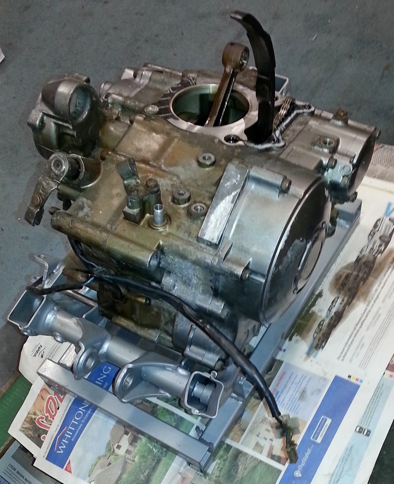
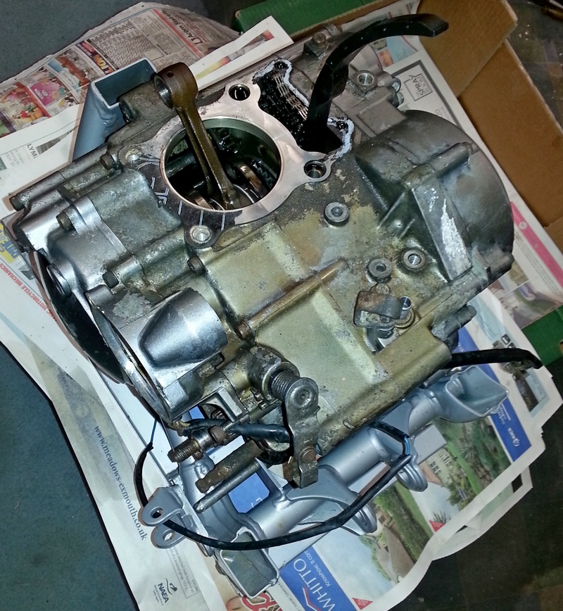
The starting point for the guide is with the engine removed from the frame and the head, cylinder barrel and piston removed.
The order of work to remove the engine from the frame is:
side covers, seat, fuel tank
carburettor and crankcase breather hose
engine guard - bashplate and frame guards if fitted
drain oil - a lot easier to do now than with the engine out!
exhaust header pipe
starter motor
clutch cable
disconnect magneto and neutral switch leads coming from the stator and the spark plug HT lead
gear shift pedal, sprocket cover and front sprocket
RH footrest and brake pedal
mounting bolts and brackets
remove engine from RH side of the TTR
turn the engine to TDC and remove the camshafts, cylinder head, cylinder barrel and piston
Pictorial guides are available showing some of the work needed to get to this point as follows:
Removing the carburettor here
Replacing the carburettor here
Removing the cylinder head here
Adjusting valve clearances here
But first make sure you start with the engine as clean as you can get it. Once the complete engine is out of the frame it is a lot easier to clean up. See here for some hints and tips.
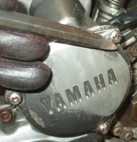
This is the starting point for this guide. The photos show the engine bottom end complete with clutch and generator covers still in place.
1. Remove the clutch cover and internals
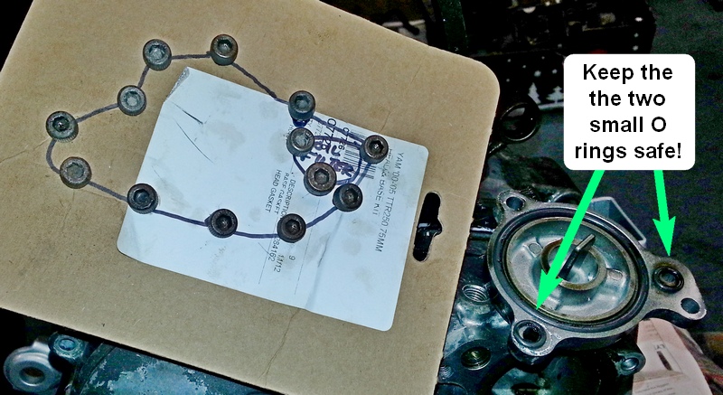
Remove the oil filter cover and clutch cover by undoing the 5mm Allen-headed bolts in a criss-cross fashion to prevent distorting the cover.
Place the bolts in a piece of marked cardboard so that you can easily get them back in their correct position.
Try not to lose the two small oil filter O rings!
You may have to give the cover a bang with a hide hammer or similar to get it loose and, if you are lucky, the big gasket will remain in one piece stuck to the cover.
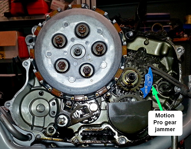
Next remove the clutch pressure plate by undoing the 5 bolts in a criss-cross pattern.
To stop the clutch assembly turning either use a gear jammer or a thick aluminium or copper washer jammed between the gears to stop them turning.
Remove the 5 bolts (10mm heads) and their springs along with the pressure plate followed by the friction and metal clutch plates.
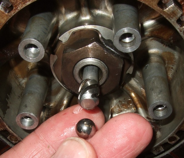
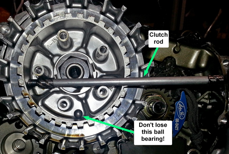
Next remove the clutch push rod and its ball bearing - don't lose the ball bearing so maybe stick it to the rod with some masking tape!
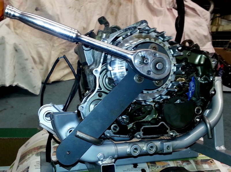
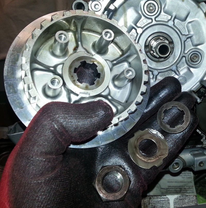
Knock back the tab washer on the centre nut with a hammer and old screwdriver, hold the clutch centre (I am using a holding tool from Totally TTRs - see here) and undo the 27mm nut.
Remove the nut, tab washer, centre plate and the thick washer underneath as shown in the photo below.
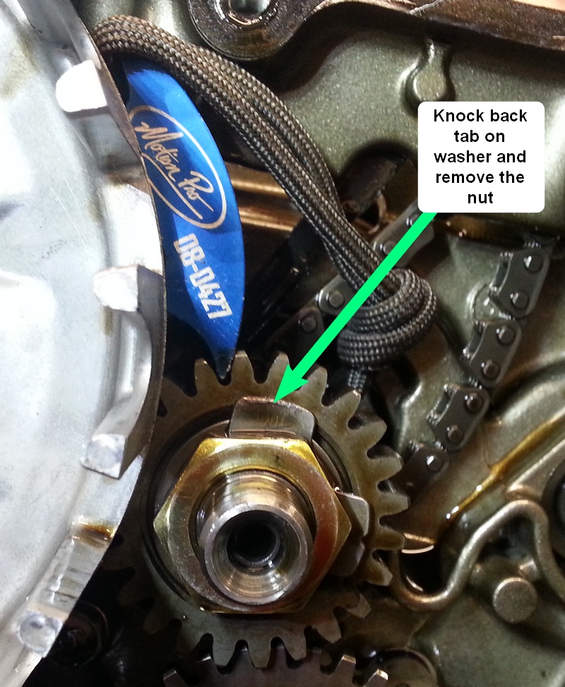
Leave the clutch centre basket on so that you can use its gear wheel to jam against the crankshaft gear and allow the 24mm nut to be removed after knocking back its tab. There is a small key that locates the gear - keep it safe!
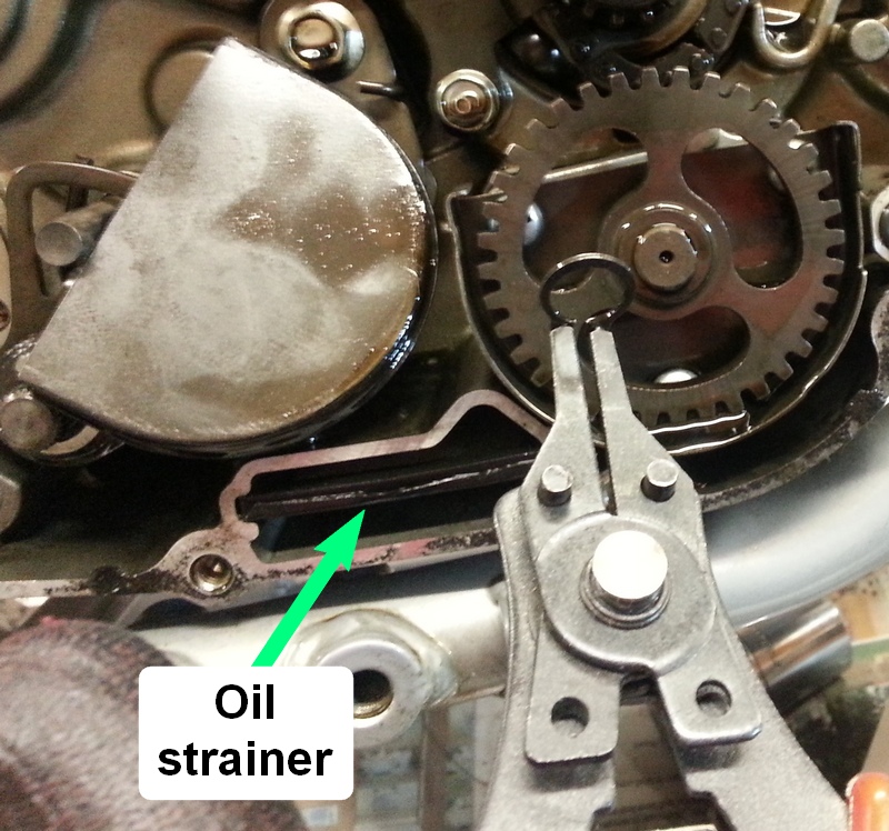
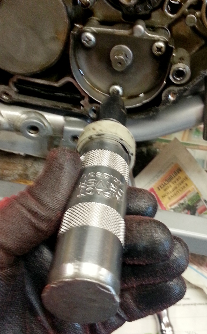
Next remove the oil pump and oil strainer. Prise the oil pump cover off being careful not to distort it. Later TTRs may not have this cover. Then remove the circlip holding the gear on and remove the gear to expose the three chromed retaining bolts. I recommend using an impact driver to remove these to prevent damaging their heads as they can be in very tight!
If the oil pump hasn't been taken off before then it might need a bit of force to lever or knock it off.
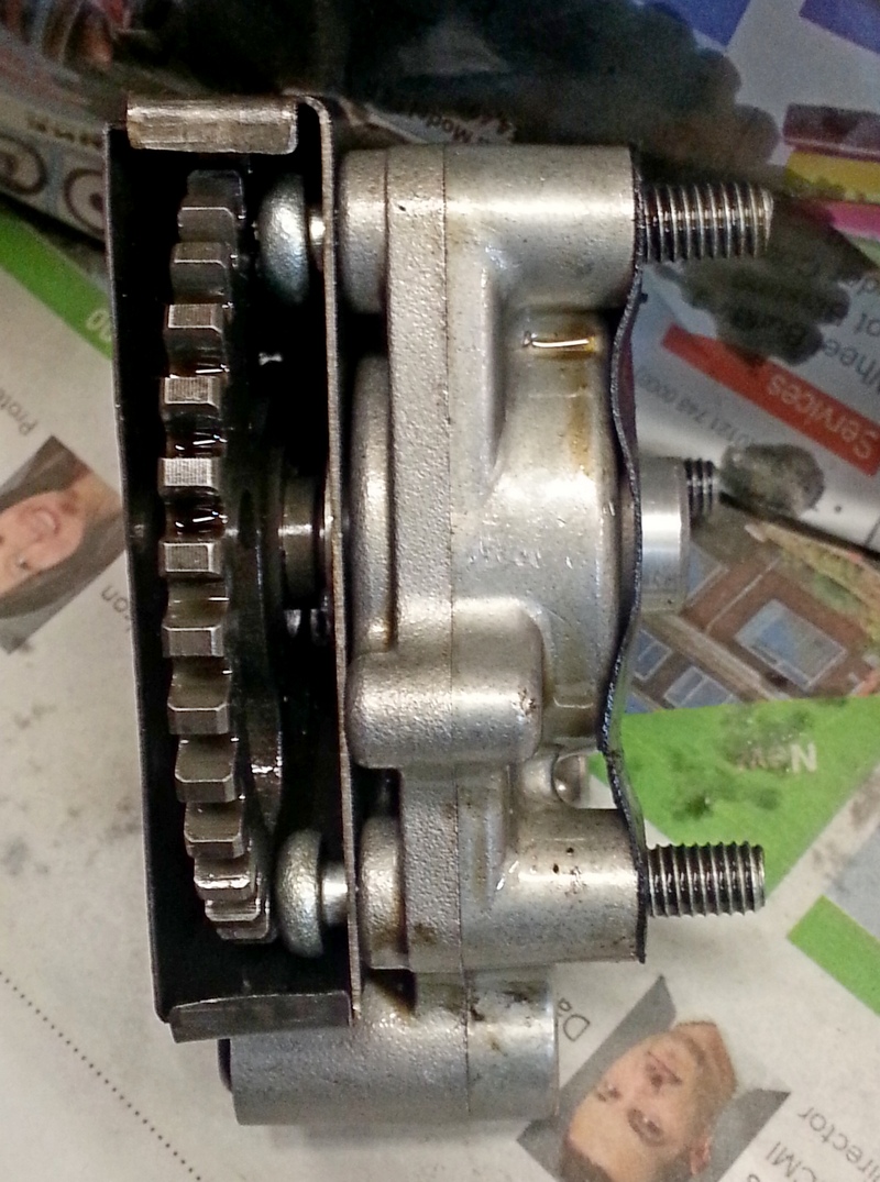
Once removed, I put all the bits back together ready for the rebuild.
Remove
(i) the shift shaft (drive axle) circlips and collar or, if fitted, the
kickstart idler gear,
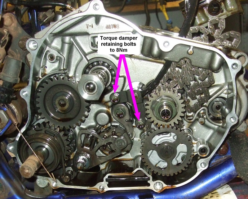
(ii) the timing chain guide by undoing the two 10mm bolts and
(iii) the gear shift lever and the washer behind it (important not to lose it!) by prising off the E-clip and sliding it off.
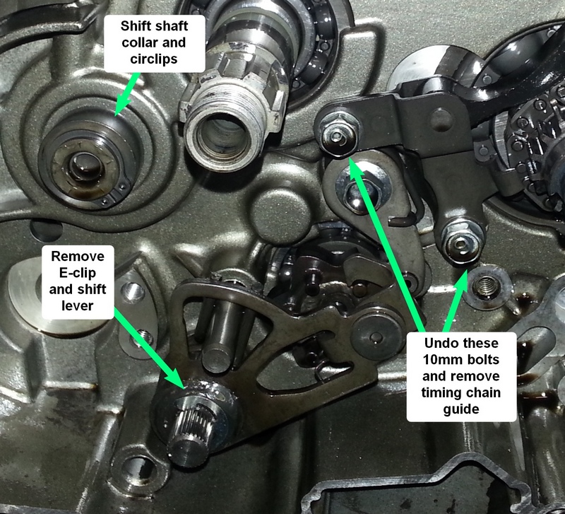
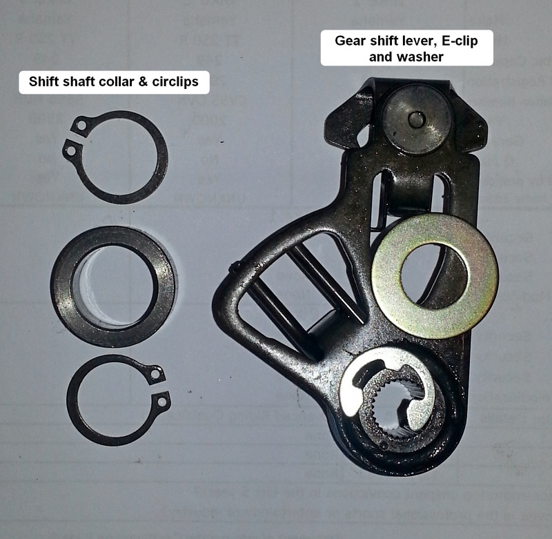
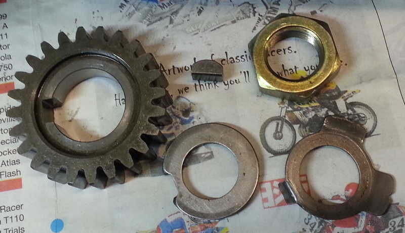
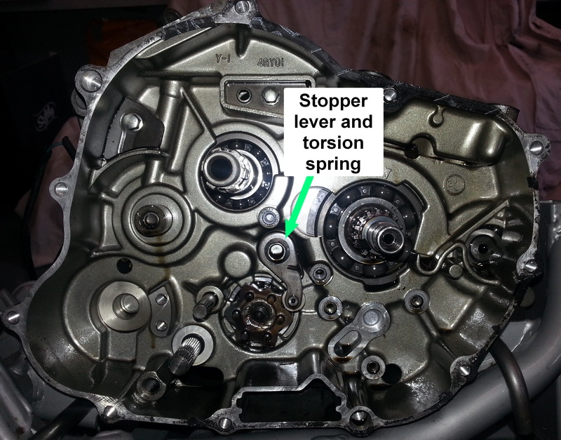
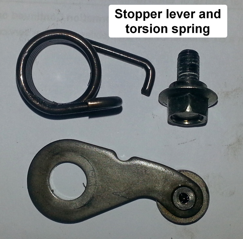
Remove the stopper lever and torsion spring and the RH crankcase is now empty!
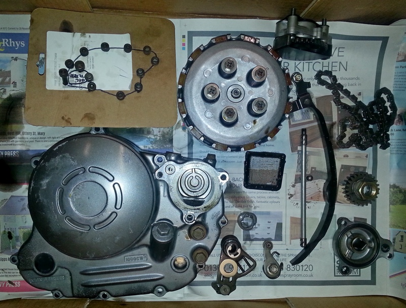
You should have a box of parts looking something like this:
2. Remove the generator cover and internals
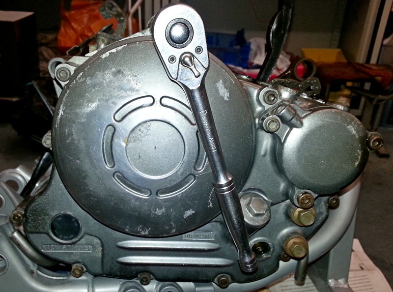
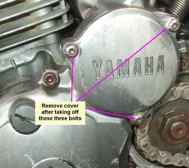
Remove the starter gear cover by undoing the 3 bolts. These can be tricky if they haven't been taken off recently. Best to start using an impact driver. If that rounds out the heads then you will have to resort to a hammer and chisel to get them turning.
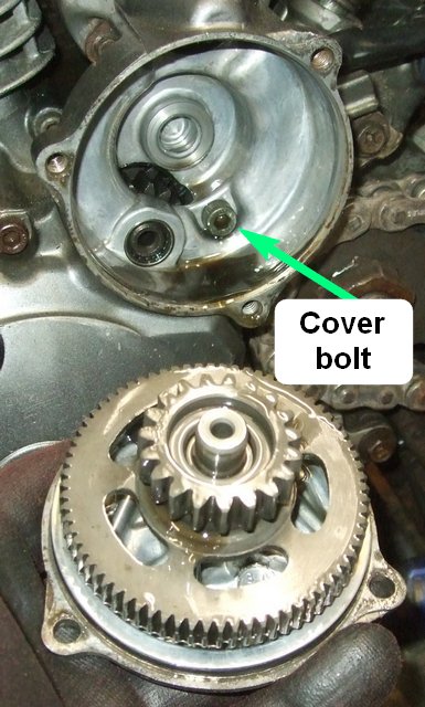
Take off the cover and remove the starter idler gear, its shaft and bearing. This exposes a bolt which helps hold the generator cover on.
Remove the generator cover by undoing the 5mm Allen-headed bolts in a criss-cross pattern starting with only a quarter turn until they undo freely.
The cover needs to be pulled off firmly as the flywheel magnet will try to hold it on!
Put the bolts on a marked piece of card as you remove them so that you know what order they go back in.
If the two locating dowels aren't tight in their housing then take them out and store them safely - preferably with the retaining bolts.
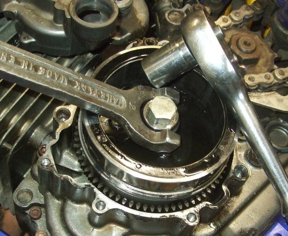
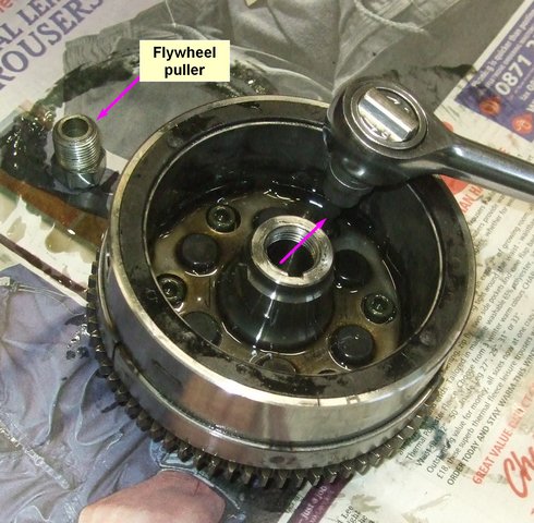
Next remove the 14mm flywheel bolt using something to stop the flywheel turning.
Then use a flywheel puller to pop the flywheel off its taper.
Remove
(i) the flywheel (and its Woodruff key),
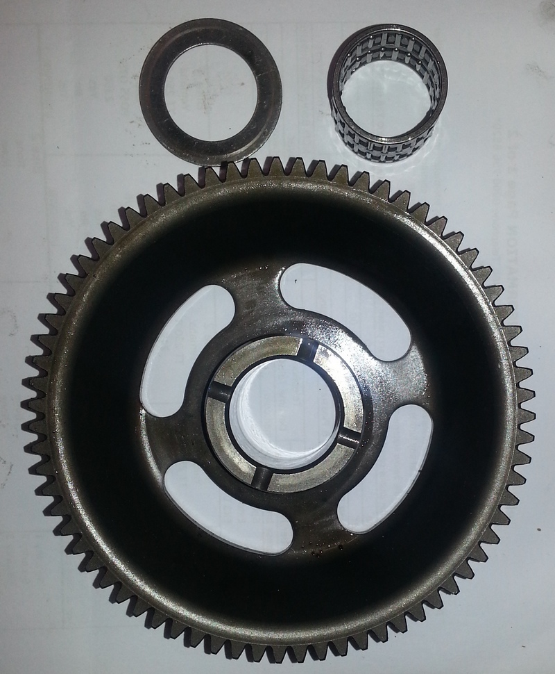
(ii) idler gear 2 with its two washers and
(iii) the large starter gear 3 and its bearing and washer.
It is easy to lose washers by accidentally leaving them in place and for them then to fall off and disappear into a dark corner of your workshop!
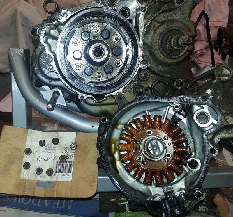
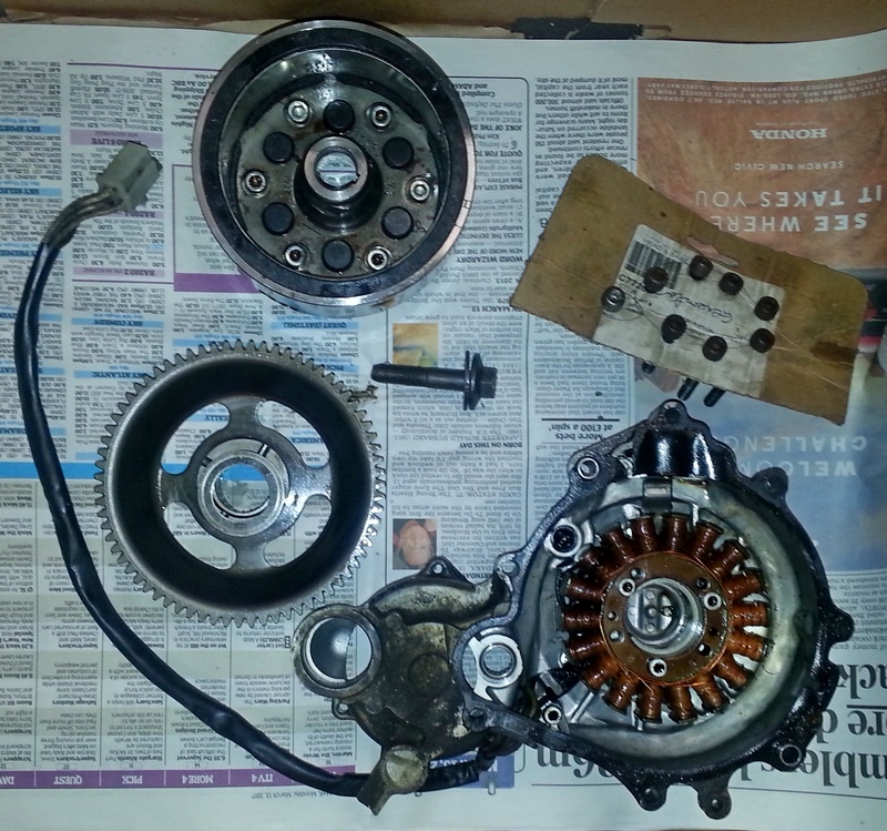
The LH crankcase is now empty and you have a box of parts looking a bit like this:
3. Splitting the crankcases
Loosen the 5mm Allen-headed bolts a quarter of a turn in a criss-cross fashion to prevent distorting the crankcases.
Once the bolts turn easily they can be spun out one at a time and pushed into a cardboard holder such that you know where each one will fit back in place.
A couple of little jobs left to do before splitting the crankcases:
(a) remove the neutral switch lead if still fitted
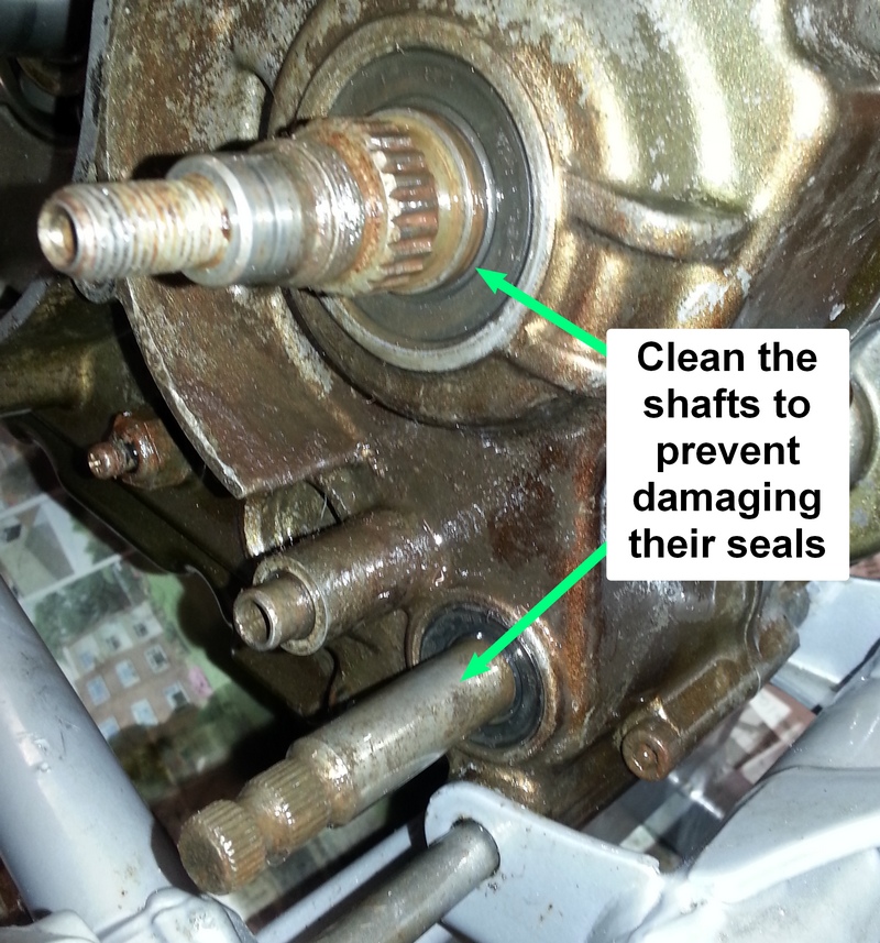
(b) clean the sprocket and gear change shafts and lube them with WD40, or similar, to prevent possible damage to their oil seals as you pull the crankcase off, and
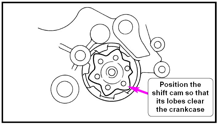
(c) make sure the shift cam is positioned such that it will pass through the case without snagging.
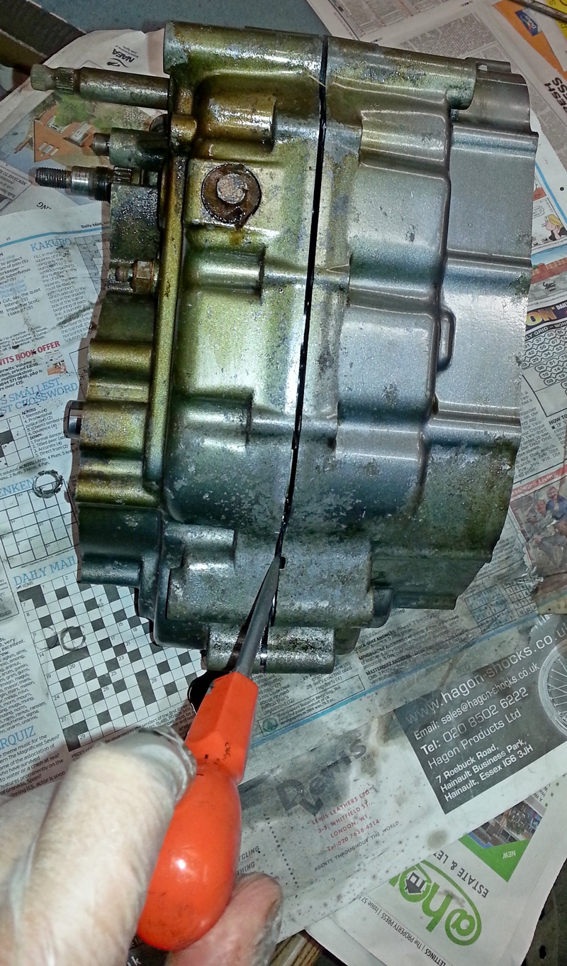
Then tap around where the cases join with a hide hammer to help them part. You will hear the hollow sound change as the joint seal is broken.
There is a safe spot that you can get a plain screwdriver in to get the process started.
It's important to make sure that the cases split in parallel, i.e. evenly all the way around, and that you make every effort to prevent any damage to the mating surfaces of the crankcases.
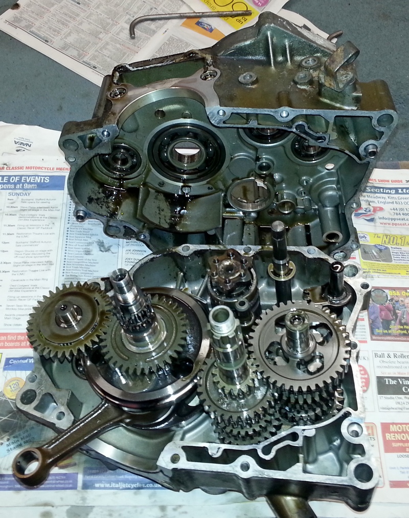
IMPORTANT: The crankshaft is a press fit in the LH case so you are lifting off the RH case leaving the gears, etc., in the LH side as shown in the photo below.
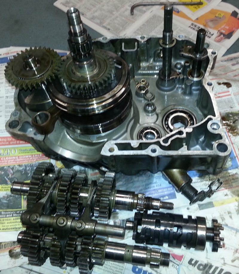
4. Remove crankshaft and gears
Try and keep the gears and selector shaft and arms together when removing the cluster if possible.
A good tip is to cable tie the whole cluster together to keep the shift forks in their correct position. Also, just in case, mark which way is up on the shift forks if you have a marker pen.
The shift shafts pull out easily but you will probably need to put some persuasion on the crankshaft to get it out of its bearing. I rest the crankcase on a flat surface with the crankshaft over the edge. Place a piece of hard plastic over the flywheel shaft end and tap the crankshaft out with a heavyish hammer. I put my hand under the crankshaft to catch it when it pops out.
The alternative is to use a crankcase separating tool which bolts into the case and a centre spindle screws in to push on the end of the crankshaft to free it. However, such a tool costs over £60 and might only be used this once. You decide!
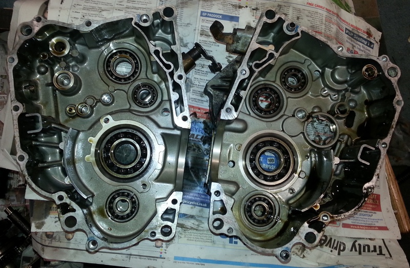
This is the point at which you need to carefully examine the bearings in the casings and replace any damaged or worn. If you decide to replace all of the bearings then the easiest way to do this is to thoroughly clean off all the oil, put the casings on some aluminium foil (or similar) and put them in the oven for about half an hour at 300°F and most of the bearings will just drop out or will do if you tap the casings on a piece of wood (to save damaging the casings).
A really good guide to removing and replacing the casing bearings by Paul Olesen can be found here
PART 2 - THE REBUILD!
5. Check internal bearings and replace if worn or damaged
Tools needed: hot air gun, rubber and metal hammers, the old bearing, and a large punch.
If you can, put the bearings in the freezer for a few days to "shrink" them. It helps if you can heat up the bearing housings (one at a time) well with a hot air gun to expand them. Then gently start to tap in the bearings and get them level with the rubber hammer. I use the old bearing as an interface between the new bearing and hammer to get the new one in without damage.
DO NOT ever hit or use the centre of a bearing to drive it home as this will ruin the bearing!
6. Fit crankshaft and gears in LH casing
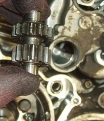
I use the large starter gear, a 3/4" socket and the flywheel bolt over the LH side of the crankshaft to pull it through the main bearing as it is an interference fit.
It is now a case of replacing parts, cleaning and checking them as you go.
If you are being fastidious, now is the time to replace the gear change and transmission shaft oil seals.
Whilst most of the bottom end parts are an easy and obvious fit, the gear clusters, shift cam and shift forks can be a bit of a challenge!
In particular it can be tricky to get the selectors in place - unless you had cable tied the gear cluster together at the dismantling stage.
It goes like this:
1. Fit the two gear shafts.
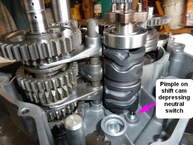
2. Fit the shift cam in the neutral position. This is when the little pimple on the end of the shift cam is depressing the neutral switch as shown.
3. If you have wisely left the shift forks on their rail during disassembly (and marked them which way is up) remove them from the rail and lay them out in their oriented positions. Otherwise they are marked C, L and R for Centre, Left and Right. The marks face upwards.
4. Fit the top fork first.
5. Then the middle one.
6. Then the lower one.
7. Next, using six fingers and a thin screwdriver, slip the rail down through the forks.
The above requires some jiggling and juggling of the shift cam and gears on the shaft, but it goes together with patience.
8. Rotate the shift cam anticlockwise about 10deg and, with a wriggle of the mainshaft,. 1st gear will engage. Turn the input shaft with one hand and check the rotation of the output shaft. Next, turn the shift cam clockwise in stages and check each gear engages in turn.
9. Return the gear set to neutral position. This is important, otherwise the other crankcase half won't go on.
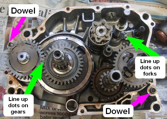
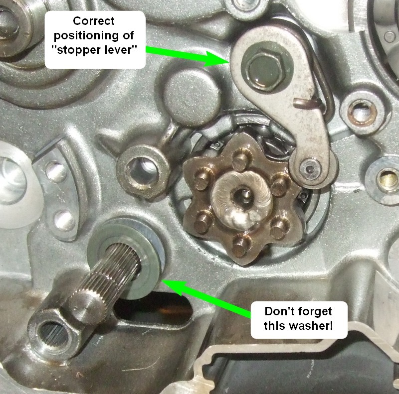
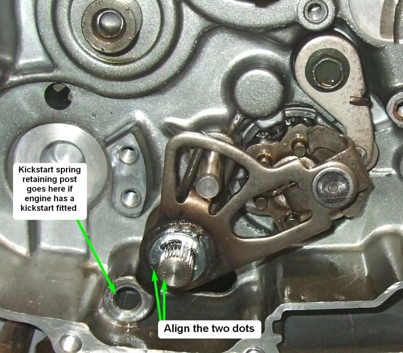
Next fit the two shift shafts, ensuring the two dots line up and fit the right hand engine case.
Make absolutely sure that you have the dots on the crankshaft/balancer cogs and gear change shafts are lined up. Also, make sure that the two locating casing dowels are in place.
Your engine should now look like this - ready to fit the other crankcase half:
7. Clean the edges of both crankcases and fit together
Give the crankcase mating faces a final clean up along with the crankcase bolts and then bolt them together after covering both sides with some non-hardening flange sealant. I use Loctite 574. Take your time as this is a critical part of the build and shouldn't be rushed.
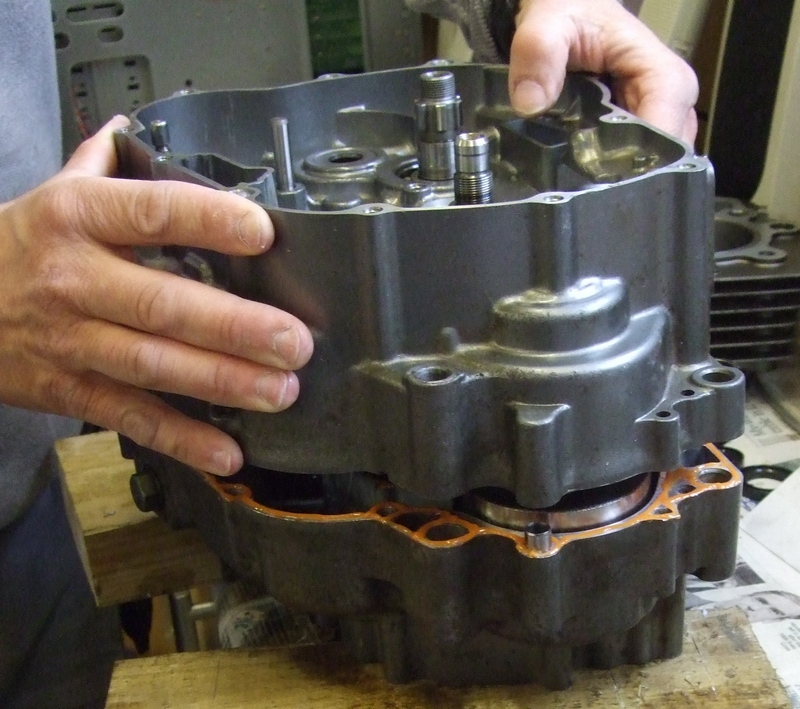
Then, with the LH crankcase side containing the crankshaft and gears in at the bottom, fit the cases together. A bit of wiggling may be required and maybe some gentle taps with a hide/plastic/rubber hammer but no substantial force should be needed. If it is, stop and investigate!
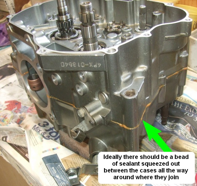
If the sealant was spread correctly then there should be a bead of it squeezed out around the whole of the mating faces.
The crankcases are sold as matched pairs and are designed by Yamaha to bolt together without a gasket but using sealant instead. It's a bit scary as you can't really test the seal is oil tight until everything is put back together and it would then be a lot of work to strip it all apart again. Thankfully I haven't had a problem so far and not heard of anyone else having experienced a leak.
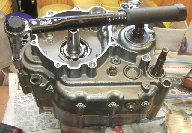
Turn the gearbox over and fit the crankcase bolts and torque them up to 10Nm.
I use some blue workshop paper soaked in clutch/brake cleaner to wipe off the surplus sealant.
8. Replace clutch internals and cover
Fit the cam chain, primary drive gear, and the timing chain guide (slipper) ready for the clutch basket to be fitted..
I always fit new timing chains to my rebuilds as they work hard and a worn chain can be the cause of noise.
Fit the clutch primary driven gear and boss.
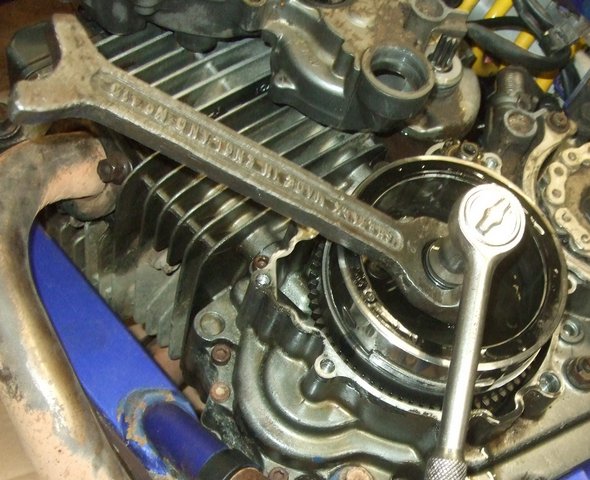
Using a gear jammer, thick copper or aluminium washer or rag to stop the gears turning, the clutch and primary drive gear nuts should be torqued up to 75Nm and 80Nm respectively.
Fit the gear selector mechanism.
Next up is to bend over the tabs on the tab washers on the clutch nut and primary drive gear. The clutch one is always difficult because of access. I use a plumbers "water pump" pliers/wrench for this job.
Refit the clutch push rod and ball bearing.
After fitting the clutch plates and pressure plate, adjust the clutch actuating arm so that the pointer lines up with the casting mark on the casing. Do it now as it is difficult to see when the engine is in the frame.
There isn't anything in the workshop manual stating what the acceptable end float is for the fitted clutch basket. It seems to vary between 1mm and 3mm on the engines I have worked on.
Fit the cleaned gauze oil filter - only goes in one way so you can't get it wrong unless you force it.
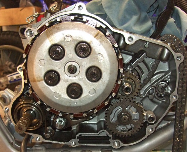
Your engine should now look like this:
Fit the two dowels and replace the cover replacing the gasket if the old one is damaged followed by the filter cover. If the O rings look a bit tired, replace them with new.
Turning to the LH side of the engine, fit the thrust washer, the large starter gear and flywheel after which the most technical part of the rebuild is over.
9. Replace generator internals and cover
If the generator cover gasket is in good shape re-use it, otherwise fit a new one. Now fit the cover making sure the stator wires are correctly located before tightening it up.
The starter gear cover can now be fitted (with some decent bolts to replace the original Allen headed ones which invariably round out) and that's the bottom end rebuild completed!
Brian SussexCompiled by Brian Sussex, Devon, UK
http://www.ttr250.com/
- all you ever wanted to know
about TTR250s
http://ttr250.activeboard.com/
- the forum for TTR250 owners
http://www.totallyttrs.com/
- everything you need (possibly!) for
your TTR250
http://www.totallywrs.com/
-
for all your WR250R and WR250X after-market parts and accessories
Reference within this site to any specific commercial or non-commercial product, process, or service by trade name, trademark, manufacturer, private individual or otherwise does not constitute or imply an endorsement, recommendation, or favour by Brian Sussex